Engineering task and calculation objective
Spherically dished covers — spherically domed, bolted heads with a bolting flange ring — are used wherever a vessel end must be removable: on manway covers, heat exchanger bonnets, reactor covers or filter covers. This module calculates spherically dished covers to ASME BPVC Section VIII Division 1, Mandatory Appendix 1-6 (spherically dished covers with bolting flanges) and determines both the required wall thickness of the spherical crown and the required thickness of the flange ring.
The special feature of a dished cover is the interaction between crown and flange: besides the pressure, the spherical shell introduces a horizontal component of its membrane force into the flange ring, which additionally carries the bolt moment from the gasketed joint. The module covers internal and full face gaskets and, for dished covers without a separate flange ring, also accounts for designs with clamp (swing) bolts. Input quantities include the crown inside radius, the knuckle radius, and the as-built head and flange thicknesses.
If you need to calculate a spherically dished cover to ASME VIII-1, Appendix 1-6 provides the formulas for the different configurations of Figure 1-6 (sketch a to d); the gasket and bolt loads are determined per the rules of Appendix 2.
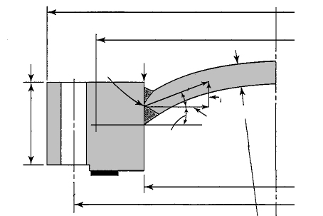
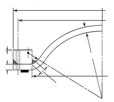
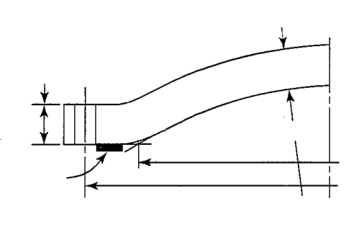
Standard and calculation basis: ASME VIII APPENDIX 1, 1-6 2025 Edition
Calculation workflow
- Select the configuration per Figure 1-6: First the design is defined: crown integral with the flange ring or welded in, gasket internal or full face, with or without a separate flange ring, or with clamp bolts. The configuration determines which formulas of Appendix 1-6 apply.
- Enter geometry and gasket data: Inputs are the crown inside radius L, the knuckle radius, the bolt and gasket data (bolt circle, effective gasket diameter, seating and operating loads per Appendix 2) and the intended as-built thicknesses of head and flange.
- Calculate the required crown thickness: The wall thickness of the spherical crown is determined from the internal pressure, the crown radius and the allowable stress of the head material; depending on the sketch, the spherical shell formula or the relation t = 5·P·L/(6·S) applies. For external pressure, or pressure on the convex side, the buckling resistance must be checked in addition.
- Determine bolt and gasket loads per Appendix 2: For the gasket seating and operating conditions, the bolt loads Wm1 and Wm2 are calculated from the hydrostatic end force, the residual gasket compression load and the seating pressure; from these follow the required bolt area and the flange moments.
- Verify the flange thickness: The required flange ring thickness follows from the flange moment and the horizontal component of the crown membrane force, which additionally loads the ring in torsion or hoop tension. The as-built flange thickness must reach the calculated minimum in both the gasket seating and the operating condition.
- Evaluate the as-built thicknesses: Finally, the module compares the as-built head thickness and the as-built flange thickness (including allowances for corrosion and undertolerance) with the calculated requirements and reports the utilization.
Input quantities
| Quantity | Symbol | Unit |
|---|---|---|
| Flange moment from 2-6 or 2-11 | M0 | N·mm |
| Calculation pressure | p0 | bar |
| Design temperature | T0 | °C |
| Outside diameter | A | mm |
| Inside diameter | B | mm |
| Bolt circle diameter | C | mm |
| Final flange thickness | Te | mm |
| Lever arm of force Hr | hr | mm |
| Crown radius | L | mm |
| Knuckle radius | r | mm |
| Final head thickness | te | mm |
| Wall thickness allowance | c1 | mm |
| Corrosion allowance | c2 | mm |
| Material | Werkstoff | – |
| Allowable stress | S | N/mm² |
| Angle of the tangent | β1 | RAD |
| Distance (bolt circle - flange inside diameter) | hD | mm |
| Axial component of the membrane load | HD | N |
| Radial component of the membrane load | Hr | N |
| Additional moment | M1 | N·mm |
| Required head thickness | t (1) | mm |
| Required thickness incl. allowances | t+c1+c2 | mm |
| Version (2,3,4 or 5) | (2-5) | – |
| Required flange thickness (ring gasket) | T(2) (2) | mm |
Calculation options
Gasket
Ring gasket · Full-face gasket
Bolting holes
Round bolting holes · Bolting holes slotted through the edge of the head
Worked example
For a spherically dished cover to ASME VIII-1 Appendix 1-6, Figure 1-6 sketch (d) (crown with bolted flange ring, internal gasket), the required wall thickness of the spherical crown is to be determined. The verification of the flange ring is then performed separately per Appendix 1-6/Appendix 2 and is not part of this worked example.
Given values
| Design pressure P | 1.0 MPa (10 bar) |
| Crown inside radius L | 1,000 mm |
| Allowable stress S (SA-516 Gr. 70, moderate temperature) | 138 MPa |
| Corrosion allowance c | 1.0 mm |
Solution
Required crown thickness
For covers per sketch (d), Appendix 1-6 gives:
t = 5·P·L / (6·S) = 5 · 1.0 MPa · 1,000 mm / (6 · 138 MPa) = 5,000 / 828 = 6.04 mm
Allowances and as-built thickness
With a corrosion allowance c = 1.0 mm, the minimum ordering thickness becomes:
tmin = 6.04 + 1.0 = 7.04 mm
An as-built head thickness of 8 mm is selected; the plate undertolerance is thereby covered.
Result
| Required crown thickness (without allowances) | 6.04 mm |
| Minimum thickness with corrosion allowance | 7.04 mm |
| Selected as-built thickness | 8 mm |
All values are illustrative. The applicable standard and project-specific boundary conditions remain authoritative.
Frequently asked questions
How does a spherically dished cover differ from a torispherical (Kloepper or Korbbogen) head?
The spherically dished cover is a bolted head: spherical crown plus flange ring with gasket. Torispherical heads, by contrast, are permanently welded-in heads without a bolted joint. For the dished cover, the complete flange and gasket problem (bolt loads, flange moment, seating and operating conditions) is therefore added to the shell calculation — which is exactly what Appendix 1-6 in conjunction with Appendix 2 covers.
What role does the direction of the crown curvature play?
The crown can be concave or convex toward the pressure. With the pressure on the concave side, the shell carries the pressure in membrane tension; with the pressure on the convex side, the crown is loaded in compression and must additionally be verified against elastic buckling per the external pressure rules. Moreover, the horizontal force on the flange ring reverses, which can change the governing flange moment.
Why must the flange be verified separately for the gasket seating and the operating condition?
In the gasket seating condition the full bolt load acts on the gasket diameter without internal pressure — the allowable stress at room temperature governs. In the operating condition, the pressure end force and the crown thrust are added, and the allowable stress at design temperature applies. Depending on the gasket (high seating pressure y), the seating condition can require the larger flange thickness.
What must be considered with full face gaskets?
A gasket extending over the full face width supports the flange outside the bolt circle as well, which changes the lever arms and the moment distribution compared to the internal gasket. The module uses a dedicated calculation procedure for this; simply carrying over the formulas for internal gaskets would not be correct.