Engineering task and calculation objective
Pipe bends and tees are the critical components of every piping stress analysis: they are more flexible than the straight pipe but at the same time concentrate the stresses from bending and torsional moments. This module calculates stresses and moments in pipe bends and tees per ASME B31.3 (Process Piping) and verifies them against the allowable stress of the material at design temperature.
The basis is the B31.3 verification equations for the load cases of sustained loads (pressure, dead weight) and thermal displacement loading: from the in-plane and out-of-plane moments and the torsional moment, the governing comparison values are formed using the stress intensification factors of the respective component. The factors differ considerably by construction type — forged tee per B16.9, welded-on branch, branch with reinforcing pad, or extruded tee. Inputs include design pressure and temperature, material and the allowable stress σall.
You need to calculate stresses in pipe bends and tees to ASME B31.3 in every flexibility analysis of process piping — for example to evaluate moment limits from a piping stress calculation, compare branch designs, or run verifications for changed operating temperatures.
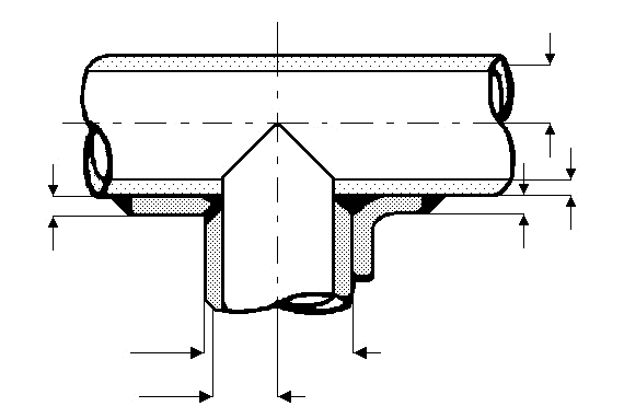
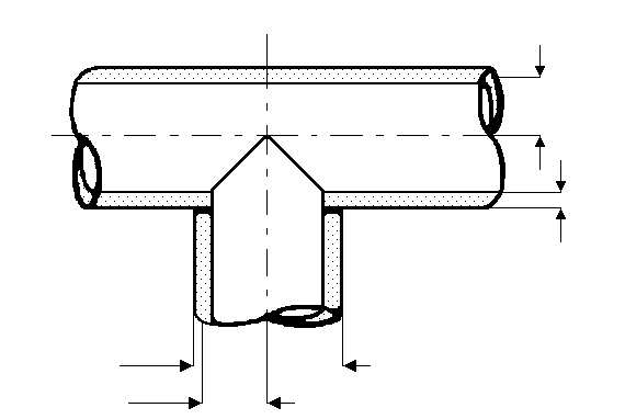
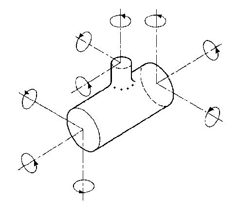
Standard and calculation basis: ASME B31.3:2022
Calculation workflow
- Define component and construction type: First the component is selected: pipe bend with radius and wall thickness, or tee in its construction type (forged per B16.9, welded-on branch, with reinforcing pad, extruded). The construction type determines the flexibility characteristic and the stress intensification factors.
- Enter design data and material: Design pressure and design temperature are entered; from the selected material follows the allowable stress at temperature. For the displacement load case, the allowable stress range is additionally formed from the values at cold and hot temperature.
- Apply the moments: The section forces known from the piping stress calculation — in-plane bending moment, out-of-plane bending moment and torsional moment — are applied separately for the load cases of sustained loads and thermal displacement.
- Evaluate the stress intensification factors: From the flexibility characteristic of the component (a function of wall thickness, radius or branch geometry), the stress intensification factors for in-plane and out-of-plane bending are determined; for the tee, different values and effective section moduli apply to the run and branch pipes.
- Perform the verifications: The resulting stresses are checked against the B31.3 limits: the longitudinal stress from sustained loads against the allowable stress at temperature, the stress range from displacement loading against the allowable stress range. The module reports the utilization per load case and location (bend, run pipe, branch).
Input quantities
| Quantity | Symbol | Unit |
|---|---|---|
| Torsion stress | σt | N/mm² |
| Resulting stress | σe | N/mm² |
| Bending stress | σb | N/mm² |
| Bending stress | σba | N/mm² |
| Torsion moment | Mt | N·mm |
| Tube Inner moment | Mi | N·mm |
| Outer moment | Mo | N·mm |
| Inside pipe diameter | di | mm |
| Outside pipe diameter | da | mm |
| Branch outside diameter | Db | mm |
| Mean tube radius | r2 | mm |
| Bending radius of pipe | R1 | mm |
| Extrusion radius of branch | rx ≥1/8*Db | mm |
| Tube thickness | T | mm |
| Branch thickness | Tb | mm |
| s_v | ≤ | N/mm² |
| s_vb | ≤ | N/mm² |
| Thickness of reinforcement | Tr | mm |
| Torsion stress | σta | N/mm² |
| Resulting stress | σea | N/mm² |
| Branch Inner moment | Mia | N·mm |
| Outer moment | Moa | N·mm |
| Torsion moment | Mta | N·mm |
| Inside branch diameter | db | mm |
Frequently asked questions
What are stress intensification factors (SIF) and why are they needed?
The SIF indicates by how much the actual fatigue-effective stress in a component exceeds the beam bending stress of the straight pipe under the same moment. Bends ovalize under bending, tees concentrate the load at the branch junction — both significantly increase the local stress. B31.3 provides geometry-dependent formulas for this; they stem from fatigue tests after Markl and are calibrated to the weld quality of typical piping components.
Why is a distinction made between in-plane and out-of-plane moments?
A bend responds to a moment in its plane of curvature differently than to a moment transverse to it: the ovalization patterns and hence the stress peaks differ, which is why each direction receives its own factors. The same applies to the branch of a tee. Applying the larger factor sweepingly to the resultant moment is conservative, but often gives away considerable margin.
Does internal pressure increase or reduce the stresses in the bend?
Both are possible: the internal pressure stiffens thin-walled, large-diameter bends against ovalization and thereby reduces flexibility and stress intensification — B31.3 permits a pressure-dependent correction of the factors for this. At the same time, the pressure itself generates longitudinal and hoop stresses that must be superimposed in the sustained load case. Treating both effects separately is essential for a correct result.
Can I use the SIF values of a forged tee for a welded-on branch as well?
No. A forged tee per B16.9 has rounded transitions and considerably more favorable factors than an unreinforced welded-on branch, whose sharp weld transition yields the highest values; reinforcing pads and extruded branches lie in between. The construction type must therefore match the actual design exactly — mixing them up is one of the most common errors in flexibility analyses.