Engineering task and calculation objective
The WRC module calculates, per WRC Bulletin 107, the additional stresses in cylindrical shells caused by external nozzle loads — forces and moments from connected piping. As an extension beyond the bulletin, the module superimposes the internal pressure stresses with the associated stress intensification factors, so that the total loading at the introduction point can be evaluated.
Nozzle loads are unavoidable in apparatus engineering: thermal expansion, dead weight, and reaction forces of the piping act on the nozzle as radial and shear forces as well as longitudinal, circumferential, and torsional moments. At the penetration, these produce local membrane and bending stresses in the vessel wall that the pure pressure design does not capture. Based on Bijlaard's shell theory, WRC Bulletin 107 provides dimensionless influence curves for calculating these stresses for each load component at defined points around the nozzle circumference — for decades the standard method for allowable nozzle loads on pressure vessels.
The module records the geometry and materials of cylinder and nozzle (outside diameters, wall thicknesses with allowances, strength values, safety factors), calculates the membrane and bending stress components of all load components, superimposes them on the pressure stresses, and compares the result with the allowable stresses — optionally with interpolation of curve values outside the chart range.
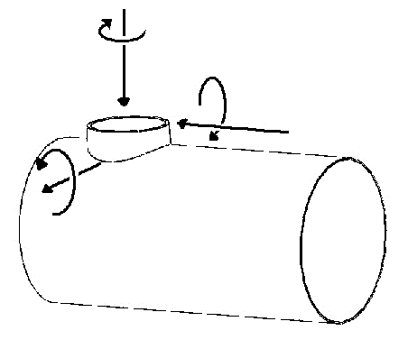
Standard and calculation basis: WRC 107
Calculation workflow
- Record geometry and materials: The inputs are the outside diameter and wall thickness of the cylindrical shell and the nozzle, including the allowances for wall thickness undertolerance and corrosion, as well as the materials with strength value and safety factor at design temperature; from these follow the allowable stresses of both components.
- Form the dimensionless parameters: From the ratio of nozzle to shell radius and the shell parameter (radius to wall thickness), the dimensionless characteristic values are formed with which the influence curves of WRC 107 are read. If the parameters lie outside the chart range, the module can extrapolate or interpolate the curve values — with a corresponding notice.
- Calculate the stresses per load component: For each load component — radial force, shear forces, longitudinal and circumferential bending moments, torsional moment — the membrane and bending stress components in the circumferential and longitudinal directions of the shell are determined at the governing points around the nozzle circumference.
- Superposition with the internal pressure stresses: The pressure membrane stresses of the shell are — as an extension beyond the pure bulletin — provided with stress intensification factors at the penetration and superimposed, with correct signs, on the stresses from the nozzle loads.
- Evaluation: The resulting equivalent stresses at all examined points are compared with the allowable values of the respective stress category (membrane or membrane plus bending). Exceedances indicate that the nozzle loads must be reduced, the nozzle reinforced (e.g. reinforcing pad), or the wall thickness increased.
Input quantities
| Quantity | Symbol | Unit |
|---|---|---|
| Radial force Circ. moment | P Mc | N |
| Shear force Long. moment | Vc Ml | N |
| Shear force Torsional moment | Vl Mt | N |
| Radial force Circ. moment | P Mc | N·m |
| Shear force Long. moment | Vc Ml | N·m |
| Shear force Torsional moment | Vl Mt | N·m |
| Outside diameter Outside diameter | Da da | mm |
| Total thickness Total thickness | T t | mm |
| Outside diameter Outside diameter | Da da | mm |
| Total thickness Total thickness | T t | mm |
| Rounding radius cylinder/nozzle for cyclic loading | r | mm |
| Factors | γ β | – |
| Factors | γ β | – |
| Membrane Bending | Kn Kb | – |
| Membrane Bending | Kn Kb | – |
| A | A | N/mm² |
| B | B | N/mm² |
| C | C | N/mm² |
| D | D | N/mm² |
| oben | oben | N/mm² |
| oben | oben | N/mm² |
| oben | oben | N/mm² |
| oben | oben | N/mm² |
| unten | unten | N/mm² |
Frequently asked questions
For which geometries is the WRC 107 method valid?
The influence curves are based on Bijlaard's theory for small attachments on thin-walled shells. They are valid for limited ratios of nozzle to shell diameter (as a guide, d/D up to about 0.3) and for common shell slenderness. With large penetrations, very thick-walled shells, or nozzles close to discontinuities (heads, ring girders, adjacent nozzles), the parameters leave the validated curve range — then WRC 297, FEA, or EN 13445 Annex V/VI are the better choice.
What does the interpolation of curve values outside the chart mean?
The original charts of the bulletin cover only a limited parameter range. Real equipment often lies just outside; the module can then extend the curves computationally. Such extrapolated values are approximations without experimental validation — they should be interpreted conservatively and, for larger exceedances of the curve range, replaced by an FEA. The module flags this case via a dedicated switch.
Where do the nozzle loads entered here come from?
Usually from the piping stress analysis of the connected line, which delivers forces and moments at every connection point for the governing load cases. In early project phases, allowable nozzle loads from tabulated standards or customer specifications are used instead. What matters is a consistent sign and coordinate convention between the piping analysis and the WRC calculation — mixing up the longitudinal and circumferential moments is among the most frequent errors.
Why is the opening reinforcement verification per AD 2000 B9 or ASME UG-37 not sufficient?
The opening reinforcement covers only the weakening of the shell by the opening under pressure. External forces and moments from the piping produce additional local bending and membrane stresses that are entirely independent of it and can considerably exceed the pressure stresses. Only the superposition of both loadings — as performed by the module — verifies the penetration completely.