Engineering task and calculation objective
The WRCK module calculates the local additional stresses in spherical shells caused by external nozzle loads – that is, by forces and moments introduced into the shell through a nozzle or a welded circular attachment. The basis is WRC Bulletin 107 and its revised edition WRC 537, which build on Bijlaard's work on local load introduction into shells. Anyone who has to calculate nozzle loads on spherical heads or spherical vessels will find here the verification method established internationally in pressure vessel engineering.
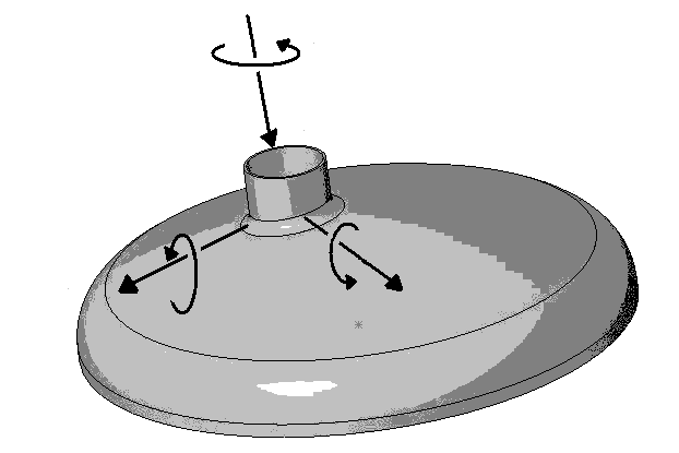
In practice, this task arises whenever connected piping transmits forces and moments to a vessel nozzle: thermal expansion of the line, dead weight, wind loads or reaction forces produce membrane and bending stresses at the penetration that can far exceed the pure internal pressure stresses. From the applied radial forces, shear forces and moments, the module determines the stress components at the nozzle/spherical shell junction at the governing circumferential positions.
As an extension of the pure WRC 107 procedure, the program can optionally superimpose the internal pressure stresses, taking into account the associated stress intensification factors, so that a complete stress evaluation at the opening is possible. The curve values of the WRC charts can, if required, also be interpolated or extrapolated outside the plotted parameter range – an option the user must activate deliberately.
Standard and calculation basis: WRC 107 / WRC 537
Calculation workflow
- Record geometry and loads: First, the spherical shell geometry (radius, wall thickness) and the nozzle dimensions are entered. The external nozzle loads are then defined: radial force, shear forces, and bending and torsional moments, as typically handed over from a piping analysis at the connection point.
- Form the dimensionless parameters: From the ratio of nozzle to shell dimensions and the wall thickness, the method forms the dimensionless shell parameters with which the curve families of WRC Bulletin 107/537 are evaluated. If the parameters fall outside the chart range, interpolation beyond the curves can be enabled; the result must then be flagged as an approximation.
- Determine stress components from the WRC curves: For each load component, the membrane and bending stress contributions in the meridional and circumferential directions at the inner and outer fibre of the shell are determined from the Bijlaard curves. The evaluation is performed at the governing circumferential positions of the nozzle attachment.
- Superposition with the internal pressure stresses: The stresses resulting from the nozzle loads are superimposed, with correct signs, on the internal pressure stresses of the spherical shell. In doing so, the module accounts for the stress intensification at the opening via appropriate stress intensification factors, which goes beyond the scope of the original bulletin.
- Stress evaluation: The superimposed stresses are combined into equivalent stresses and compared with the allowable values customary for local membrane and secondary stresses in the applicable code context (e.g. the ASME categorization into Pm, Pl and Q). Exceedances indicate that the nozzle reinforcement, the wall thickness or the allowable piping loads must be adjusted.
Input quantities
| Quantity | Symbol | Unit |
|---|---|---|
| Radial force Moment | P M1 | N |
| Shear force Moment | V1 M2 | N |
| Shear force Torsional moment | V2 Mt | N |
| Radial force Moment | P M1 | N·m |
| Shear force Moment | V1 M2 | N·m |
| Shear force Torsional moment | V2 Mt | N·m |
| Outside diameter Outside diameter For dished heads outside diameter of sphere equals outside diameter of crown | Kugelaussendurchmesser | mm |
| Total thickness Total thickness | T t | mm |
| Outside diameter Outside diameter For dished heads outside diameter of sphere equals outside diameter of crown | Stutzenaussendurchmesser | mm |
| Total thickness Total thickness | T t | mm |
| Rounding radius shell/nozzle | r | mm |
| (Membrane) | γ Kn | – |
| (Bending) | ρ Kb | – |
| (Membrane) | γ Kn | – |
| (Bending) | ρ Kb | – |
| A | A | N/mm² |
| B | B | N/mm² |
| C | C | N/mm² |
| D | D | N/mm² |
| oben | oben | N/mm² |
| oben | oben | N/mm² |
| oben | oben | N/mm² |
| oben | oben | N/mm² |
| unten | unten | N/mm² |
Frequently asked questions
What is the difference between WRC 107 and WRC 537?
WRC 537 is the revised edition of WRC 107, published in 2010 with editorial and computational corrections. The underlying Bijlaard methodology is identical; WRC 537 corrects known errors in the curves, provides the curve values as evaluable equations, and clarifies the sign conventions. For new calculations, WRC 537 should be cited as the reference; the results are practically identical to a correct WRC 107 evaluation.
For which geometric ratios is the method valid?
The bulletin's curves are prepared only for certain ranges of the dimensionless parameters, in particular for sufficiently small ratios of nozzle diameter to sphere radius and for thin-walled shells. Large openings (roughly d/D well above 0.5) and very thick-walled shells lie outside the validated range; there, FEM analyses or other methods are indicated. The interpolation beyond the charts available in the module is an engineering approximation and should be documented and critically assessed in the results.
Where do the nozzle loads I have to enter come from?
Usually from a piping flexibility analysis (e.g. to EN 13480 or ASME B31.3), which delivers forces and moments at each connection point. Alternatively, vessel manufacturers specify allowable nozzle loads, which are then verified with WRCK. What matters is a consistent sign and coordinate convention between the piping program and the WRC evaluation – this is where the most frequent errors occur in practice.
Does the WRC calculation replace the opening reinforcement verification for internal pressure?
No. The opening or reinforcement verification for internal pressure according to the applicable vessel code (AD 2000 B 9, EN 13445-3 or ASME VIII) remains separately required. WRCK deals with the additional local stresses from external loads and their superposition with the pressure stresses; the two verifications complement each other.