Engineering task and calculation objective
The ZICK module calculates saddle supports of horizontal cylindrical vessels using the Zick method – the procedure published by L. P. Zick in 1951, which to this day forms the basis of practically all code approaches to saddle calculation (including ASME Section VIII and the associated WRC literature). Anyone who wants to calculate the saddle support of a horizontal pressure vessel or storage tank uses it to verify the stresses in the vessel shell at the support locations as well as the saddle structure itself.
In practice, the saddle calculation is an integral part of every horizontal vessel design: the vessel acts as a beam on two supports whose dead weight and contents produce longitudinal bending stresses at the saddle plane and at mid-span. At the saddle horns, additional local circumferential bending stresses arise, which are frequently design-governing. The module accounts for the vessel geometry including head type, the saddle spacing, the contact angle of the saddle and of an optional wear (reinforcing) plate, as well as stiffening rings.
Beyond the classic Zick analysis, the program also captures additional external loads: g-force components in the longitudinal, transverse and vertical directions (e.g. from earthquake or transport), forces from wave motion for ship-mounted or offshore-supported equipment, and restraint forces from foundation flexibility (spring rate and head deflection of the pier). The anchor bolt calculation, with the friction coefficient between saddle and concrete and the allowable bearing pressure on the concrete, is also included and can be output separately on request.
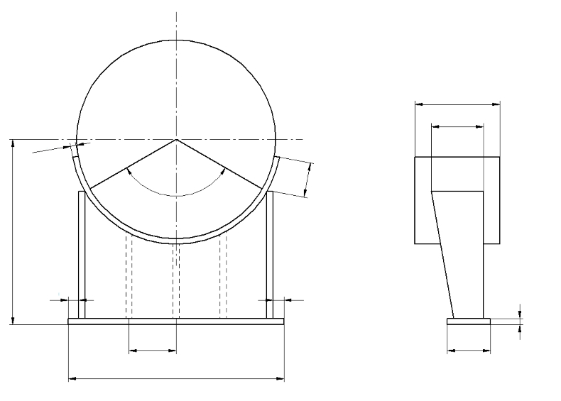
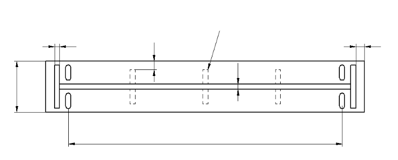
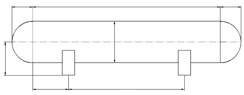
Standard and calculation basis: WRC Saddle Zick
Calculation workflow
- Define vessel and saddle geometry: The inputs are the shell radius or mean shell radius, wall thickness, head type and the spacing of the saddles. The contact angle of the saddle (typically 120° to 150°) and the angle of an optional wear plate determine how severe the local stresses at the saddle horn become; stiffening rings can be considered as an alternative.
- Assemble the loads: Dead weight, contents and operating pressure yield the operating load on the saddles. In addition, g-force ratios in the longitudinal, transverse and vertical directions, forces from wave motion, and longitudinal saddle forces from foundation deflection are applied. From these, the program forms the maximum longitudinal force, the maximum transverse force and the governing support reaction as the maximum of the two load cases Q1 and Q2.
- Longitudinal bending stresses per Zick: The vessel is treated as an overhanging beam on two supports. The longitudinal bending stresses in the shell are calculated at the saddle plane and at mid-span, each superimposed with the axial stress from internal pressure. The head type enters the coefficients via the stiffening effect of the heads and the load distribution.
- Shear and circumferential stresses at the saddle: Near the saddle, the tangential shear stresses in the shell as well as the circumferential stresses at the saddle horn and at the lowest point of the shell are determined. Whether a wear plate participates in carrying load depends on its contact angle and width; stiffening rings fundamentally change the stress distribution and are captured with their own coefficients.
- Verify the saddle structure and anchor bolts: The saddle web is verified for the horizontal splitting force and the transverse loads according to the chosen design. For the base plate, the bearing pressure on the concrete is checked against the allowable value, and the anchor bolts are sized from the longitudinal and transverse forces, applying the friction coefficient between saddle and concrete. This anchor bolt calculation can also be displayed in isolation.
- Evaluate the results: All stresses are compared with the allowable values for tension, compression (stability) and shear. Where limits are exceeded, typical remedies are a larger saddle angle, a wear plate, stiffening rings or a changed saddle spacing; the equations used can be output for documentation.
Input quantities
| Quantity | Symbol | Unit |
|---|---|---|
| Head Type | Head | – |
| Type of Web | Type | – |
| Stiffening Rings | Rings | – |
| Pressure | Pressure | – |
| Weight Calculation | Calc | – |
| Outside Diameter of Vessel | OD | mm |
| Corroded Thickness of Shell | ts | mm |
| Internal Design Pressure | P | MPa(p) |
| External Design Pressure | Pe | MPa(p) |
| Tangent to Tangent Length of Vessel | L | mm |
| Depth of Head | H | mm |
| Distance from Head Tangent to Saddle Center Line | A | mm |
| Height from vessel centerline to bottom of saddle | B | mm |
| Corroded Thickness of Head | th | mm |
| Design Wind Speed | V | m/s |
| Importance Factor | I | - |
| Exposure | Exp | – |
| UBC 1997 Seismic Zone | Z | – |
| Importance Factor | I | - |
| Soil Coefficient (SA, SB, SC, SD, or SE) | Sc | – |
| Installation Temperature of Vessel | Tinst | °C |
| Minimum Temperature of Vessel | Tmin | °C |
| Maximum Temperature of Vessel | Tmax | °C |
| Coefficient of Friction between Saddle and Concrete | u | - |
Calculated results
| Quantity | Symbol | Unit |
|---|---|---|
| Mean Radius of Shell | Rm | mm |
| Radius of Shell | Rs | mm |
| Saddle Spacing | Ls | mm |
| Saddle Angle | θ | ° |
| Angle of Wear Plate | θW | ° |
Calculation options
Head Type
Flanged and dished · Elliptical · Hemispherical
Type of Web
Centered · Offset
Stiffening Rings
No · Yes
Pressure
Internal pressure only · Internal & external pressure
Weight Calculation
Automatically estimated · Manually entered
Exposure
A – City Center · B – Urban and suburban area · C – Open terrain · D – Flat unobstructed areas
UBC 1997 Seismic Zone
Not to be considered · 1 · 2 · 3 · 4 · 5
Soil Coefficient (SA, SB, SC, SD, or SE)
SA – Hard Rock · SB – Rock · SC – Very dense soil and soft rock · SD – Stiff Soil recommended · SE – Soft Soil
Frequently asked questions
Why is the stress at the saddle horn so often design-governing?
At the saddle horn, the supporting action of the saddle ends abruptly, and the unsupported upper shell region carries the load through local circumferential bending. The bending stress arising there grows strongly with a small contact angle and a thin shell. Remedies are a larger saddle angle, a wear plate that is sufficiently wide and extends far enough around the shell, or stiffening rings.
When may the wear plate be credited as load-sharing?
Only if it extends sufficiently beyond the saddle on both sides – in the common codes, the contact angle of the plate must exceed the saddle angle by a minimum amount (typically at least 12°, i.e. roughly saddle angle plus 12°) and the plate must have a minimum width in the longitudinal direction. Otherwise the plate merely shifts the critical location to its own edge without effectively lowering the horn stress.
What role does the position of the saddles relative to the heads play?
If the saddles sit close to the heads (rule of thumb: distance from the head less than about half the radius), the heads act as stiffeners and significantly reduce the local stresses at the saddle. A large saddle spacing, on the other hand, increases the longitudinal bending stress at mid-span. The saddle position is therefore always a compromise, which the calculation captures through the Zick coefficients.
What are the inputs for the spring rate and deflection of the foundation used for?
For vessels on tall foundation piers or on flexible structures (e.g. ship and offshore applications), the deflection of the pier head generates additional longitudinal forces on the saddles, because one saddle acts as the fixed support and the other as the sliding support. Using the spring rate of the pier and its head deflection, the module calculates this restraint force and superimposes it with friction, wind and g-forces to obtain the maximum longitudinal force.
Does the Zick method also cover the internal pressure verification of the shell?
No. The wall thickness design for internal or external pressure is still performed to the applicable vessel code (AD 2000, EN 13445-3, ASME VIII). The Zick calculation merely superimposes the pressure membrane stresses with the stresses from the saddle support and verifies the combined values; both calculations belong together in the vessel documentation.