Engineering task and calculation objective
The Pedestal module (AHAB) calculates vessels standing on a single, central cylindrical support element — for example a support skirt or pipe leg arranged centrally under the dished end. The calculation is based on WRC Bulletin 537 for the local stresses at the load introduction point and on AD 2000-Merkblatt S3/3 — a sheet of the German AD 2000 pressure vessel code — for vessels on support skirts and legs.
The central support introduces the entire operating weight as well as moments from wind, attachments, or agitators point-wise into the dished end (Klöpper or Korbbogen torispherical head). At this introduction point, local membrane and bending stresses arise which superimpose on the stresses from internal pressure — a case not covered by the pure pressure design of the head. WRC Bulletin 537 provides the influence functions for calculating the stresses from forces and moments at cylindrical attachments; it is the refined re-issue of the classic WRC Bulletin 107.
The module determines all stresses occurring at the introduction point, in the support itself, and at the base plate with its anchorage, compares them with the allowable stresses of the respective component, and evaluates the utilization. This allows a centrally supported vessel to be fully verified to the AD 2000 code and WRC 537.
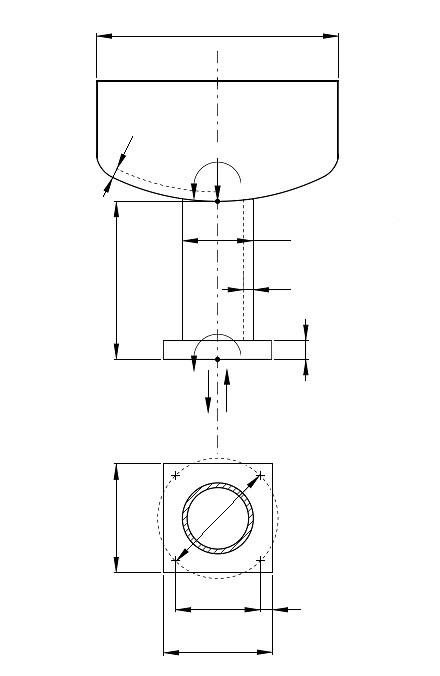
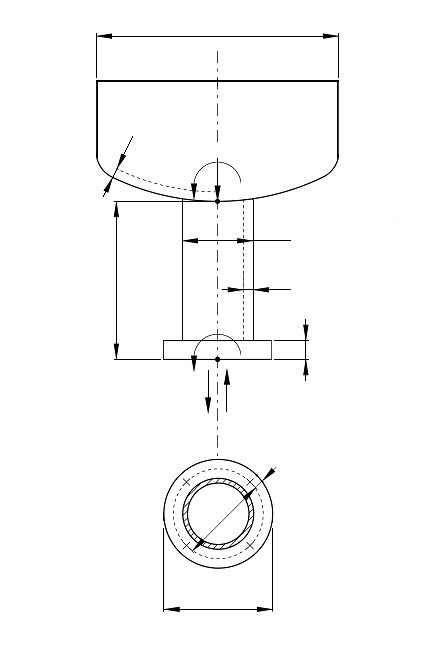
Standard and calculation basis: WRC 537 & AD 2000 S3.3
Calculation workflow
- Compile the loads: Recorded are the operating weight of the vessel including contents and attachments as well as external forces and moments, for example from wind, an agitator, or connected piping. They form the combination of internal forces acting at the support element: axial force, shear force, and bending moment.
- Local stresses at the dished end: Per WRC 537, the local membrane and bending stresses in the vessel wall at the connection of the cylindrical support element are determined from the introduced forces and moments — as a function of the ratio of support diameter to the crown radius of the head and of the wall thickness.
- Superposition with the pressure stresses: The local stresses are superimposed on the membrane stresses from the design pressure of the vessel; the resulting equivalent stresses are compared with the allowable values of the respective stress category.
- Verification of the support element: The cylindrical support element itself is verified per AD 2000 S3/3 for compression, bending, and stability (buckling); openings in the skirt for access or piping reduce the load-bearing cross-section.
- Base plate and anchorage: Finally, the base plate (circular or rectangular) is verified for bending and bearing pressure, and the anchor bolts for tension from the overturning moment. All utilization ratios are reported per component.
Input quantities
| Quantity | Symbol | Unit |
|---|---|---|
| Type of head | Bodens | – |
| Material | T | – |
| Temperature | T | °C |
| Internal excess pressure of head | p | MPa(p) |
| Outside radius | r0 | mm |
| Mean radius | Rm | mm |
| Outside diameter | Db | mm |
| Factor a | aM | – |
| Factor b | bM | – |
| Factor c | cM | – |
| Factor d | dM | – |
| Factor e | eM | – |
| Factor f | fM | – |
| Factor g | gM | – |
| Factor h | hM | – |
| Factor i | iM | – |
| Factor j | jM | – |
| aP | aP | – |
| bP | bP | – |
| cP | cP | – |
| dP | dP | – |
| eP | eP | – |
| fP | fP | – |
| gP | gP | – |
Calculated results
| Quantity | Symbol | Unit |
|---|---|---|
| Wall thickness of head | Tb | mm |
| Shell parameter | U | - |
| Nondimensional Moment | YM | - |
| Nondimensional Force | YF | - |
| Thickness of base plate | Tp | mm |
| Stress due to moment | σM | MPa(p) |
| Stress due to force | σF | MPa(p) |
| Total stress | σMFp | MPa(p) |
| Strength condition bolts | Schrauben | – |
| Stress in one bolt | σBo | MPa(p) |
| Stress due to pressure | σp | MPa(p) |
| Wall thickness of leg | Ts | mm |
| Strength condition moment | Moment | – |
| Strength condition force | Kraft | – |
| Strength condition force and moment | Moment | – |
| Strength condition pressure | Druck | – |
| Stress in leg | σF | MPa(p) |
| Tensile force of anchor bolt | FK | N |
| Proof of stability for leg not required acc. to DIN18800. | 800 | – |
| Proof of stress in leg | Fuß | – |
| Existing concrete compression simplified proof | σB | MPa(p) |
| Allowable concrete compression (default C25) | fB | MPa(p) |
| Proof of concrete compression | Betonpressung | – |
| Geometrical condition diameter of base plate | Fußplatte | – |
Calculation options
Type of head
Kloepper type · Korbbogen type · Elliptical head
Base plate
Circular plate · Square plate
Frequently asked questions
What is the difference between WRC 107 and WRC 537?
WRC 537 is the refined re-issue of WRC 107 published in 2010: the influence functions underlying the charts were formulated as equations, reading errors of the old curves were eliminated, and the range of validity is documented more clearly. The mechanics — local stresses from forces and moments at attachments on shells — is the same; results per 537 are more reproducible and suitable for programming.
Why is the central single support more critical than a support skirt under the vessel rim?
A skirt near the rim introduces the weight into the stiff transition region between head and cylinder. The central support, by contrast, hits the flattest, most flexible region of the dished end: there, even moderate forces produce considerable local bending stresses, and the superposition with the pressure stresses of the head can become design-governing. That is why the local stress verification per WRC 537 is indispensable here.
Which load cases should be examined as a minimum?
Besides the operating condition (full weight, operating pressure, wind or agitator moments), the test condition with water fill and the start-up/empty condition with maximum moment at low stabilizing weight must be considered. For the anchorage, the load case with minimum weight and maximum overturning moment is usually governing; for the head loading, the one with maximum weight.
Are there limits to the applicability of the WRC method at the dished end?
Yes. The influence functions are valid for limited ratios of attachment diameter to shell radius and wall thickness; very large support diameters relative to the head, or load introductions close to the knuckle, lie outside the validated range. In such cases — or under cyclic loading requiring a fatigue analysis — an FEA is the appropriate alternative.