Engineering task and calculation objective
The UG28 module calculates the maximum allowable external pressure for cylindrical shells, tubes and spherical shells to ASME BPVC Section VIII Division 1, paragraph UG-28. Vessels under external pressure – vacuum vessels, the jacket spaces of jacketed equipment, or columns operating under internal vacuum – do not fail by yielding but by elastic or plastic-elastic buckling. The design procedure therefore follows a completely different logic from the internal pressure calculation to UG-27.
To calculate a cylindrical shell under external pressure you need not only the diameter and wall thickness but also the unstiffened length of the shell course, because the critical buckling stress depends strongly on the ratios L/Do and Do/t. From these ratios the strain factor A is determined, and the stress factor B is read from the material- and temperature-dependent charts of ASME Section II Part D (Table G and the associated chart family, CS-1 etc.). Since the required wall thickness cannot be solved for in closed form, the module determines it iteratively.
The module reports the allowable external pressure with and without the hydrostatic head, the required wall thickness to UG-28, the minimum thickness check to UG-16, and the required wall thickness including allowances. Appendix 1 additionally covers alternative design checks.
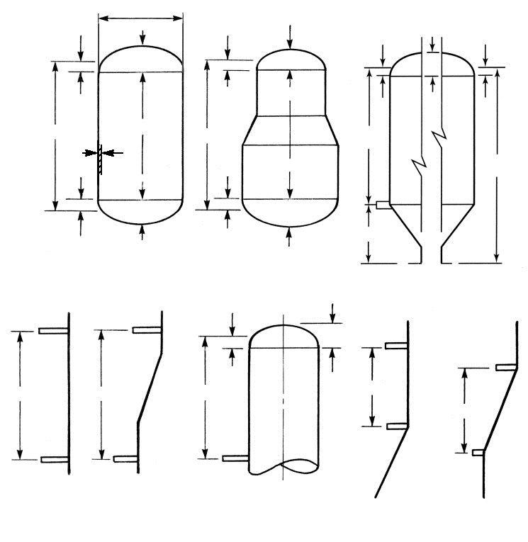
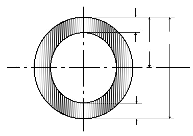
Standard and calculation basis: ASME BPVC VIII-1 UG-28 & Appendix 1: 2025
Calculation scope
- Thickness of cylindrical shells and tubes under external pressure
- Thickness of spherical shells under external pressure
Calculation workflow
- Define geometry and operating data: Outside diameter, actual wall thickness, unstiffened length (for cylinders), design temperature and external overpressure are specified. Corrosion and manufacturing allowances are subtracted from the nominal wall thickness; the calculation runs with the wall thickness excluding allowances.
- Form the geometric ratios: For cylinders the ratios L/Dₒ and Dₒ/t are formed, for spherical shells the ratio Rₒ/t. These ratios determine whether elastic buckling or plastic failure governs.
- Read factor A from the geometry chart: From the geometric ratios the dimensionless strain factor A is determined according to the chart in ASME Section II Part D, Subpart 3 (Table G). It represents the critical buckling strain of the ideal shell.
- Determine factor B from the material chart: Using factor A, the stress factor B is read from the material-temperature chart of the material in use. If A falls to the left of the start of the curve, B is calculated from the modulus of elasticity (purely elastic buckling).
- Calculate the allowable external pressure: The allowable external overpressure Pₐ follows from factor B and the geometric ratios – for cylinders with Dₒ/t ≥ 10 via Pₐ = 4B/(3·Dₒ/t). The module reports the allowable pressure with and without the hydrostatic head.
- Iterate the required wall thickness: The wall thickness is varied until the allowable external pressure just reaches the required design pressure. In parallel the module checks the minimum wall thickness to UG-16; the larger value plus allowances is the required as-built wall thickness.
Input quantities
| Quantity | Symbol | Unit |
|---|---|---|
| External calculation pressure | p0 | MPa(p) |
| Calculation temperature | T0 | °C |
| Outside diameter | D0 | mm |
| Buckling length | L | mm |
| Material | Werkstoff | – |
| Allowable stress | S0 | MPa |
| Applicable material chart | Fig | – |
| Modulus of elasticity | E | MPa |
| Design wall thickness | te | mm |
| Wall thickness allowance | c1 | mm |
| Allowance (corrosion) | c2 | mm |
| Spec. Min. Yield | Sy | MPa |
| External design pressure | pD | MPa(p) |
| Hydrostatic head | Dp | MPa(p) |
Calculated results
| Quantity | Symbol | Unit |
|---|---|---|
| Effective thickness | t0 | mm |
| Ratio | L/D0 | – |
| Ratio | D0/t0 | – |
| Factor | A | – |
| Factor (see material chart) | B | MPa |
| Factor 2*Min(S0;.9*B) | S | MPa |
| Allowable excess pressure | P | MPa(p) |
| Required thickness | t | mm |
| Tip radius | R0 | mm |
| Ratio | R0/t0 | – |
| Remark | 1 | – |
| Required thickness incl. allowances | t+c1+c2 | mm |
| Allowable pressure without hydrostatic head | MAWP | MPa(p) |
| Required thickness acc. UG-16 | tUG-16 | mm |
| Required thickness acc. UG-28 | tUG-28 | mm |
Frequently asked questions
Why can't I calculate the wall thickness under external pressure directly from a formula?
The allowable external pressure depends, via factors A and B, on graphically defined buckling charts that are material- and temperature-dependent and cannot be solved in closed form for the wall thickness. The code therefore prescribes a trial-and-error procedure: assume a wall thickness, calculate the allowable pressure, compare it with the required pressure and adjust the thickness until the check is satisfied.
What length should be used as the unstiffened length L?
L is the distance between effective lines of support – these can be stiffening rings to UG-29, the knuckle line of a formed head (with one third of the head depth counting as a contribution), or tubesheets. An unstiffened length set too large leads to unnecessarily thick walls; one set too small is unsafe if the assumed stiffeners do not meet the moment-of-inertia requirements of UG-29.
Does UG-28 also apply to partial vacuum?
Yes. Even if the vessel is evacuated only occasionally or partially (e.g. during steam-out or draining), the maximum possible external differential pressure must be applied. For vacuum design, ASME requires design for the governing differential pressure; full vacuum of 1 bar is customary unless vacuum breakers or similar devices are qualified.
How does the spherical shell calculation differ from the cylinder calculation in UG-28?
For spherical shells the length effect disappears; factor A is formed directly from A = 0.125/(Rₒ/t) and the allowable pressure from Pₐ = B/(Rₒ/t). Spherical shells buckle axisymmetrically, so stiffening rings play no role – only radius, wall thickness and the material chart govern.